by Josh Robertson
SAFETY FIRST
The first thing when it comes to electrical controls is your safety. Electricity will kill you. 0.1 amps is enough to stop your heart. Working in electrical cabinets, even the simplest ones with DC power supply can draw this easily. Checking voltages with a voltmeter goes a long way to keeping you alive. Even if the power is off, there could still be stored electrical energy in capacitors so always check voltage.

When people do not check for voltage is when people get hurt. I was going through a panel where I work one day and I had it off for a few minutes. I made the assumption that all the voltage in the drive would have drained off already. Drive was off, PLC off, no indicating lights. Went and started checking connections and got a nasty shock. Was like what the hell. Grabbed my meter and there was still 190VAC present in the control panel. It quickly drained after I put the meter on it. But still comes as a surprise to see it when I have been around them for awhile. When checking voltages, always check phase-to-phase and phase-to-ground. Good routine to get into.
The Voltmeter/Digital Multimeter (DMM)
The first piece of electrical test equipment to acquire is a Digital Multimeter (DMM). They are also called voltmeters, by a voltmeter only checks voltage. Most meters are the market today are capable of measuring at minimum: resistance, AC Voltage, DC Voltage, AC Current, and DC Current. When measuring current, on most meters, it involves breaking the circuit and placing the meter in line with current flow. This is how they work. DO NOT DO THIS!! The preferred method for measuring current is using a clamp on meter. You clamp the meter around the wire and it will read off the current. A lot safer and quicker.
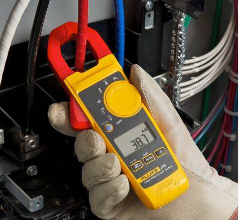
For a beginner, I would recommend a Fluke 325 Clamp Meter as shown, or Klein CL800, or Milwaukee 2237-20. They all measure AC and DC current which you never know when you need to measure DC current on DC motors. Most clamp meters only measure AC current. It also measure AC and DC voltage, frequency, temperature, resistance and capacitance. Get a
meter that will handle stuff now and later. You do not want to go back and buy another meter for DC current later. As you can see in the picture above, measuring current could not be easier. Clamp the meter around a wire and measure the current draw on that leg. I personally have a Fluke 336 which is no longer available. Does AC/DC Current, AC/DC voltage and resistance. Does the basics I need it to do. Does not do everything like 4-20mA currents for control and capacitance, but does do the job 95 percent of the time. If your just starting, do not worry about that other five percent.
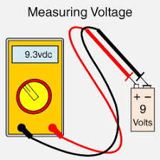
Measuring voltage is what is done most of the time with DMM’s. Something as simple as measuring the voltage on a battery is done by putting the probes in the meter, selecting the proper range, i.e. DC Voltage, and then measuring the voltage. If you are measuring AC voltage say from an electrical outlet, put your leads into the receptacle and you should measure the voltage. I know I skipped a lot like ARC flash, but that should be done by companies should be doing to ensure the safety of their employees and not something that is read online. My previous company, all maintenance personal were required to do ARC Flash video training once a year. Current company, been there almost two years and have not had it yet. Let’s say our cabinet is the ever convenient 480VAC/277VAC, which means 480VAC phase-to-phase and 277VAC phase-to-ground when measured with your DMM. These will vary slightly but are nominal values. Your cabinet is not working. You measure all three phases to ground, you have 277VAC on each phase. Noting works. If you measure phase-to-phase, you should have 480VAC between each phase. If you do not, you lost a fuse. Control transformers will send one voltage’s leg through the transformer, not power up the transformer, but give you voltage on the opposite leg. Just something that happens.
ELECTRICAL SCHEMATICS

We are done with basic electrical safety. Be safe. Work Safe. Follow company’s Lock Out Tag Out (LOTO) procedures. We move onto electrical schematics or we will just call them prints. Now above is the prints for a piece of equipment where I work that had incomplete prints. Stuff was not really correct on it. So I got tasked with redoing the prints and the cabinets. All we have is a VFD that controls a motor. We have start, stop, and a potentiometer to control the speed. Lights are used to indicate statuses and relays to separate out signals. Wires and components are labeled by line number. Now on a simple print such as this, it would be really hard to get lost following the prints. This is one sheet. Not a lot going on. Now make it ten pages, things start getting complicated. Make it 100 pages, now you get to begin to see the fun. A good set of prints will always label everything by line number, in the US. European style prints use a grid system mostly to navigate the prints. The references will refer to a sheet and then the appropriate grid coordinate’s. Both do the same.
I watched some short video one day by some guy that said the wires should be labeled as where they go. I disagree. You do that in 100 page print, your labels will be long, and you will never find it in the prints. Wire numbers relate to page and lines. I have a wire number 1620. With just that information looking inside the cabinet, you should know where it comes from, where it goes, what it does. 1 stands for sheet. With this only being one sheet, pretty simple to get to the correct page. 62 stands for the line number. Look for line 62. 0 stands for when the first time the wire number changes. On the beginning of the line, we are running 24VDC on wire number 1351. There is proximity sensor on that line PRS162, that feeds an output on wire 1620. That in turns on a relay, CR162. The wire afterwards is 1360, which is the 24VDC common signal. With the numbers 1351, and 1360, I should be able to look on lines 35 and 36 and see a component there. These are the wire numbers that feed our signal. Relay CR162 has a Normally Open (NO) contact on 1-77. Go to line 77 and there is the contact.
These are the basics of print reading and troubleshooting. Measure voltage to find where you have your signal. If I am trying to figure out why my safety relay SF166, is not coming on, I would look at my three contacts for Relays CR 159, CR161, and CR162. I see that CR162 is not on. Check voltage on the coil of the relay and I do not have 24VDC. Go check to see if the proximity sensor is made. If it is, make sure the proximity sensor is good and has an output. Could be that the sensor is not made, the sensor is bad, or the wiring between the sensor and relay is bad. Since this is proximity sensor, it uses an M12 Eurofast connector that supplies the voltage and signal for it. This is just a small example of using prints to troubleshoot through a problem. Before I got in maintenance, I knew how to read electrical schematics using resistors and transistors. Control schematics never touched. Never was taught, but learned on my own how to read them. Learned about the wire numbers and how they coincide with pages and line numbers. They are not hard to read and will go a long way into get far in this field. Learning how to read prints helps with reading PLC ladder logic.

Leave a comment