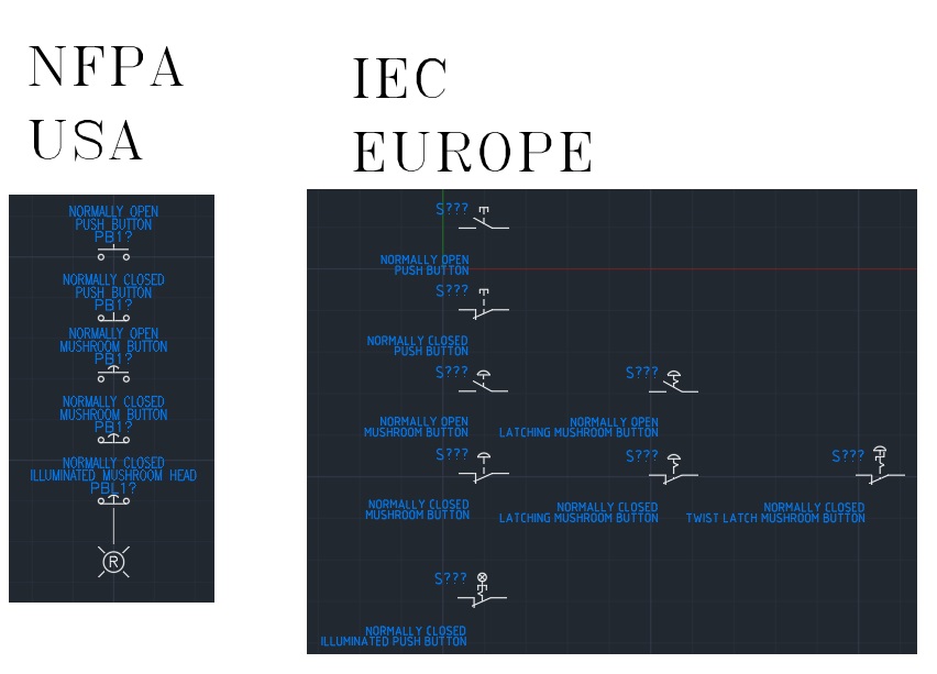
To start, depending on where you live in the world, there are different symbols used in electrical panel schematics. The United States uses NFPA symbols while Europe uses IEC. With companies being global nowadays, it is not uncommon to see machines using prints from different regions. I will be focusing on NFPA due to the fact I am located in the United States. They are also a lot easier to get started to read. An E-Stop button on machine is a Normally Closed Mushroom Head Button. There is one symbol in NFPA, even if it is latching like it is. In IEC we could have up to four different symbols for an E-Stop. I did not include a Keyed Latching Normally Closed Mushroom Button. Learning to read prints, you really do not want to get bogged down in the small details like what kind of mushroom button it is. What is going to happen we start designing circuits going through the symbols that are used.
FIRST CIRCUIT: The Light
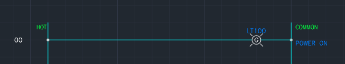
Indicator lights are on every basic machine. They always tell you what they mean in a good system. Our light is green in color and it’s whole purpose is tell us the power is on. All lights will display the color they display, G for Green, R for Red, B for Blue, A for Amber, Y for Yellow, and W for White. I really have not seen any other colors used. We could have used any color to display that power is on, but most standards I see are either green or white. It is a boring circuit though.
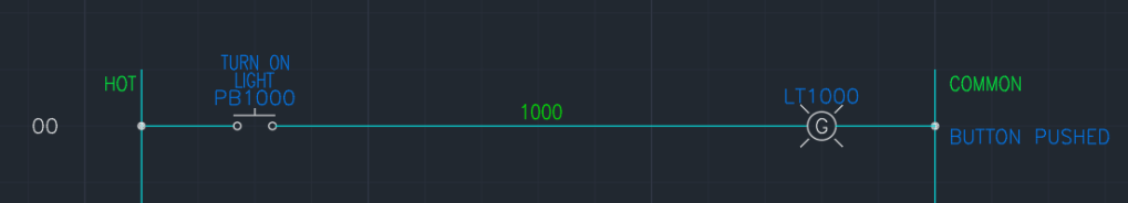
Now we have normally open (NO) push button used to turn on a light somewhere. We could of had an illuminated push button when you push the button it turns on its light such as…
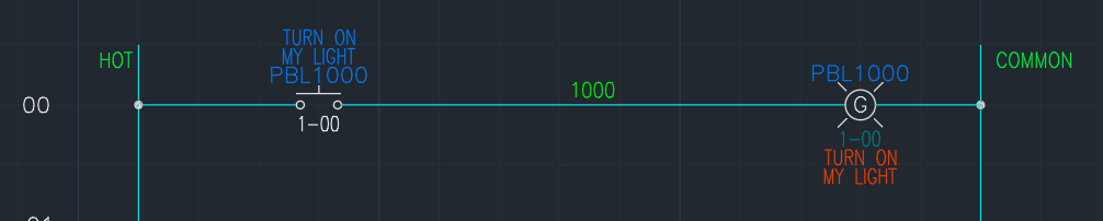
or
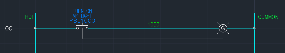
Both mean the same thing. One uses a references while another uses a line to show they are connected. Now looking the push button, there is no indicator what color it is. A system that is designed correctly will have all the buttons and lights labeled. There will multiple buttons and lights of the same color on them. Labels make sure we know what they do. So there would be a button on the panel that is labeled “TURN ON MY LIGHT” that illuminates itself green. Button will more than likely have a green lens color due to the color to display. But you do not want to push the button all the time turn on the light. You want it to stay on until you turn it off.
KEEP THE LIGHT ON
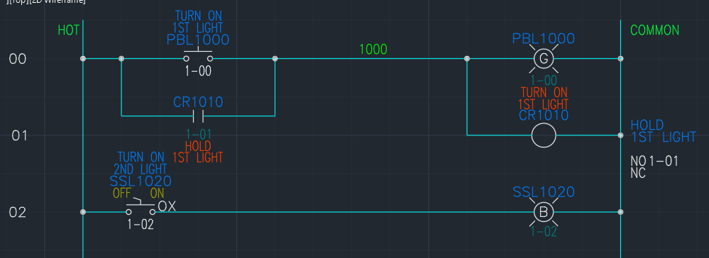
Now we have to introduce a few more symbols. Selector Switches, relay coils, and contacts. Selector switches come in many flavors, but all have the same basic symbol. The concept of the Selector switch is the light switch in your house. Turn it on, and the light comes on. Turn it off, and the light turns off. Our selector switch turns on its blue light. Selector switches can can be maintained or spring return, which is it returns back to the basic position. They can also have multiple positions 2-position and 3-position are very common, but can also be 4, 6 and 8 depending on the what it is needed to do.
Relays are extremely common in control circuits. They also come in multiple flavors, Single-Pole Double-Throw (SPDT), Double-Pole Double-Throw (DPDT), Triple-Pole Double-Throw (3PDT) being the most common. Relays work by energizing a coil to switch contacts. In a relay’s off state, the normally open (NO) contacts are inactive and the normally closed (NC) contacts are active.
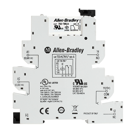
Relay designations: SPDT, DPDT and 3PDT, stand for the number of contact sets on the relay. A SPDT relay will have one set of contacts, with the contacts having a common point and a NO and NC contact. a DPDT will have two sets of contacts with two commons. Each contact set are not physically connected to each other unless someone connects them. A SPDT relay will have a NO contact on connection points 11 and 14, and a NC contact on connection points on 11 and 12. A DPDT relay contact set 1 would be 11 and 14 NO, 11 and 12 NC; contact set 2 would be 21 and 24 NO, 21 and 22 NC.
When the coil is energized, the NO contacts are active and the NC contacts are inactive. In our example above, CR1010, has an NO contact branched around the the push button. When we push our TURN ON 1ST LIGHT button, it will turn on the light and activate the relay. The relay’s contacts close and hold the circuit on. Unfortunately, we cannot turn the light off. Once it is on, it is on. This is bad design. Our selector switch allows us turn off the light.
THE SEAL-IN CIRCUIT
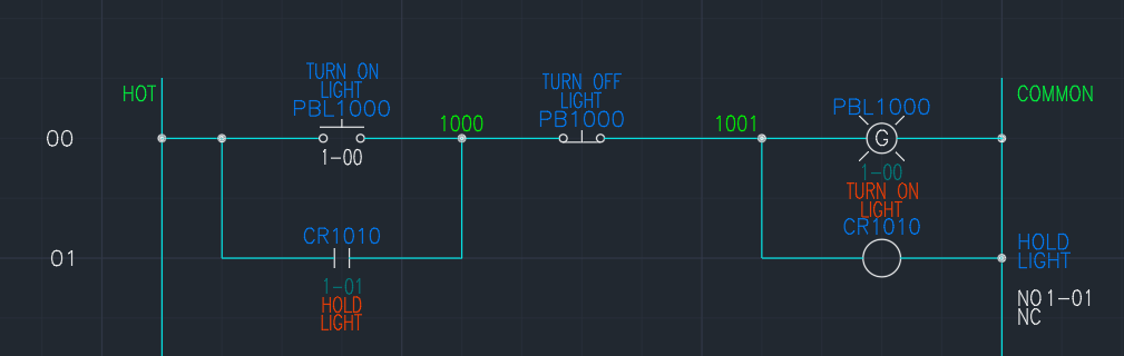
The simplest control circuit. We add a NC push button. This circuit, if we push the button TURN ON LIGHT, the light will turn on and stay on even if let go of the button thanks to the relay. If we want to turn off the light we push the button TURN OFF LIGHT. The NC contacts of the button we deenergize the coil as soon as it is pushed. These are the routinary basics of a control circuit.
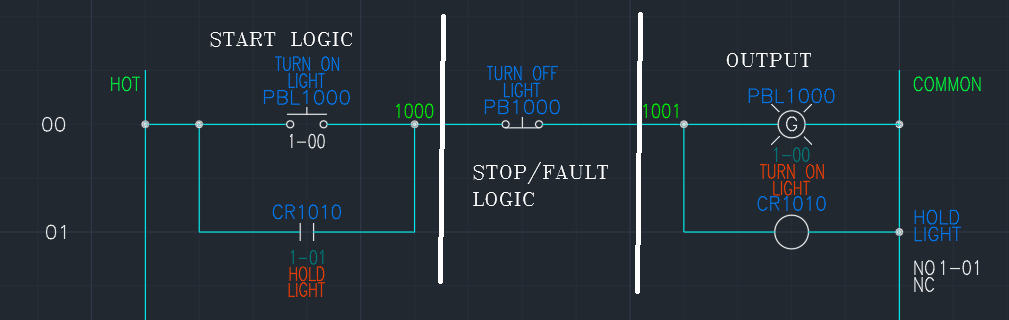
The seal-in circuit has three parts to it. The Start logic, Stop/Fault logic, and the output. We could put the stop/fault logic before the stop and that is perfectly acceptable. The start logic part, has all the requirements needed to start the circuit. These are things that are not always required to keep the circuit going.
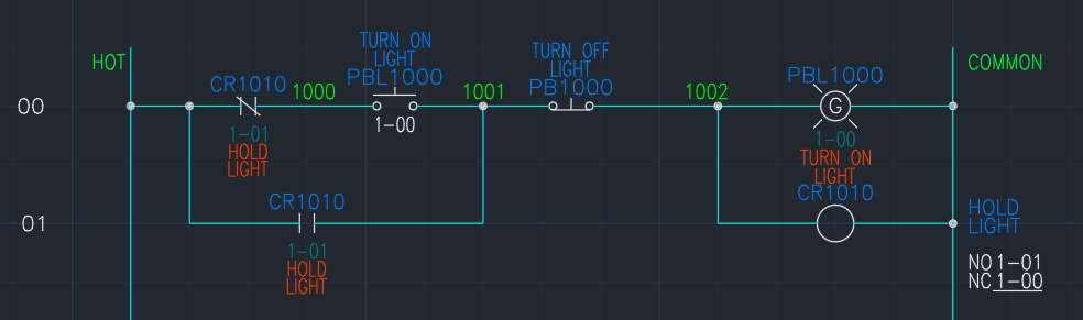
Adding the NC contact of the relay in front of the TURN ON LIGHT button does not affect how the circuit works. All the NC contact does is say make sure it is not on before trying to turn it on. When we push the button when the light is off, the NC contact opens up, but the light stays on because the NO contact is keeping the circuit going.
The stop/fault area of the circuit, are things that will cause the circuit to fail. The TURN OFF LIGHT button is our only thing we have in this circuit, but we could have multiple buttons to turn off the light or some other logic that we could use to turn off the light.
TODAY’S SYMBOLS
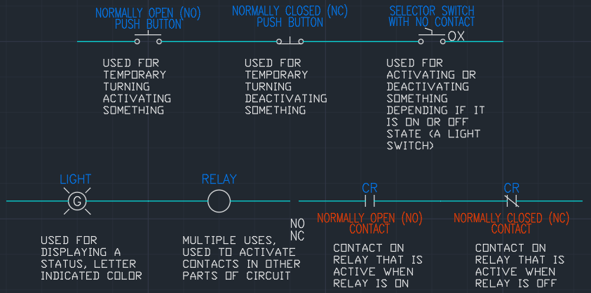
These are the basic symbols used in schematics. Not all these symbols are used in every print. With HMI’s and PLC’s, there might not be any of these as an HMI can display any light and be used for buttons and switches while the PLC is used for the relays and contacts. This is unlikely due to issues like if you are not looking at an HMI screen, you will not see the warning, where an indicator light turns on, it can quickly be seen.

Leave a comment