We left off with the most basic objects in a control panel: relays, contacts, lights, push buttons and operator switches. But a panel just turning on a light is kind of boring. Control panels are usually used to control some type of motor. Motors, depending on what their type, can be controlled by multiple means. In low voltage situations, voltages under 600VAC here in the states, the most common 480/460VAC 3-Phase (3Φ), 240/230/220/208 3Φ, 230 1Φ (single phase), 120 VAC 1Φ, and the multiple of DC motors out there (most common for industrial is 90VDC and 180VDC). Different manufactures will put different voltage ratings on their motor like 460 VAC or 480VAC. A motor with either will run 460VAC or 480VAC when connected operated by just a contactor or a manual motor starter. Just do not stick a motor for 240 3Φ on a 480 3Φ system. Will not work. A large of motors can be either wired up for 480 3Φ or 240 3Φ.
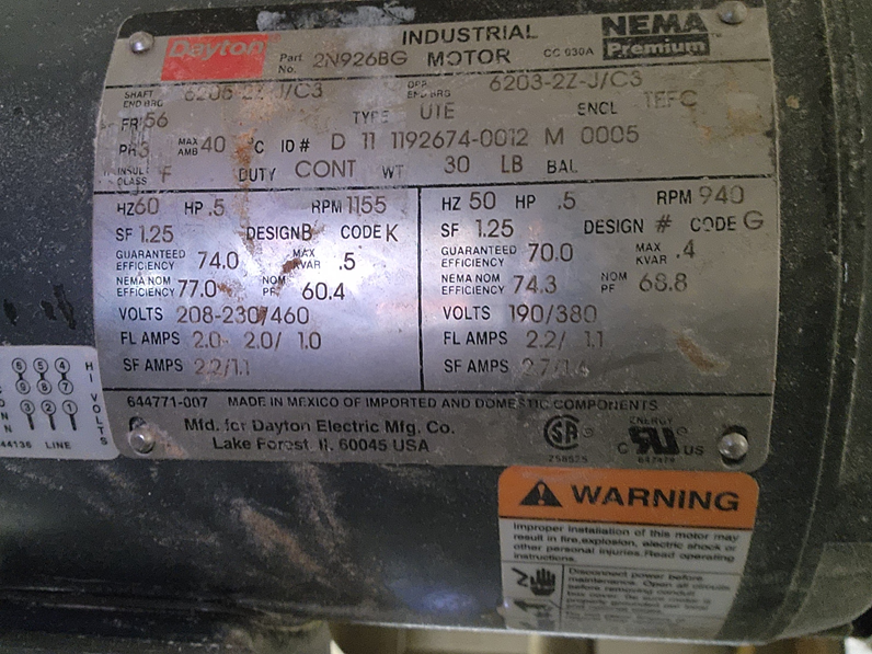

This motor on the left is for 3Φ systems of 60Hz (North America) or 50Hz (Europe mainly), voltages between 208 and 230VAC or 460VAC. 60Hz and 50Hz are frequencies of the electrical system. Motors will run at this frequency of the electrical system it is connected to. A 50Hz motor connected to a 60Hz system will run at 60Hz and a 60Hz motor connected to a 50Hz system will run at 50Hz. Frequency dictates how fast a motor will run. So 60Hz is faster than a 50Hz. It is a 1/2 HP motor and pulls 2 amps at lower voltages and 1 amp at the higher voltages when fully loaded. The only other two things of importance is the frame, 56, and the RPM’s 1155. There is a lot more info on here but we are staying with the basics right now. Frame is only relevant if you are connecting it to gearbox and you need to swap it out. The motor on the right is for 115VAC 1Φ systems, is 1/15HP, and pulls 0.75 amps. Each of these motors has a specific purpose and use.
SINGLE-PHASE MOTORS
There are various ways to start a motor: relay, switch, drive, and contactors. Starting with single-phase motors, there is no real way to industrially control the speed of a single phase motor. Yes I know there are the fans that run at different speeds with the control of a switch or fan controller, but in industrial settings those are not reliable enough. Single-phase motors are either on at max speed or off, so the easiest way to run them is relay or a switch.
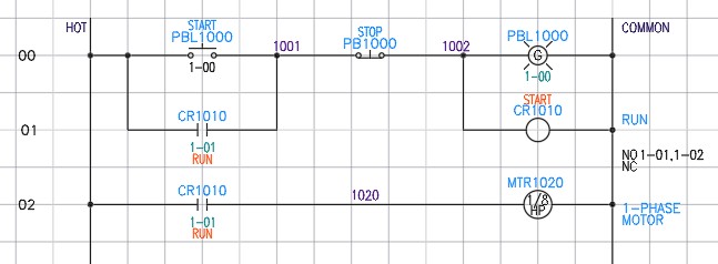
I do want to emphasize the hot and the common are usually not the same. If we were using 120VAC for control voltage and a 120VAC 1Φ motor then this circuit would be correct. Just know that the in most cases, the control voltage is not the same as the motor voltage. There is also one other glaring issues with this circuit, no circuit protection. There should be a fuse or circuit breaker in line to protect the motor and wiring incases there is too much of a load placed on the motor.
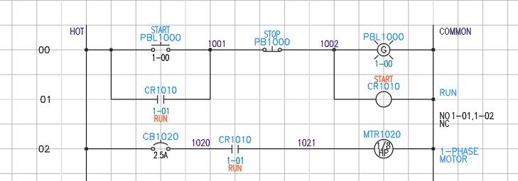
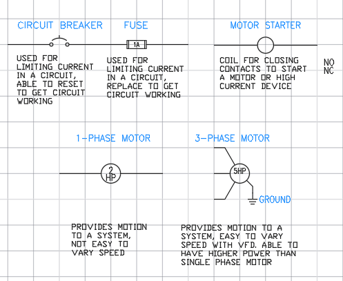
We placed a circuit breaker in the circuit to protect the wiring from overloads that can happen from a motor. It also limit the amount of current a motor can pull incase the motor has too big a load on it. If the load on the motor is more than what it can handle, it will pull more current can cause the breaker to trip. Remove the excess load, reset the breaker and the motor is good to run again. If there is something wrong with the motor after clearing the load, the breaker will trip again.
THREEE-PHASE MOTORS
Three-phase motors are the most popular motors used in industrial applications. You can connect them the drives to vary the speed of them. There is no one solution to controlling a three-phase motor. The most basic is a control circuit that is using a voltage different from the motor voltage.

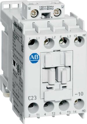
The symbol used for a motor contactor (starter) looks the same as that for a relay. All a motor contactor in its simplest form is a relay meant to handle higher currents. Sometimes a contactor is used instead of a relay due to current handling. A picture of a typical contactor is shown to the left. Most contactors are 3PST (Triple pole, Single throw) with an auxiliary contact. Contactors usually have options to have additional auxiliary contacts on them. Usually the additional contacts do not handle the currents of the contactor itself. And are used for feedback or signals to other parts of a circuit. The big difference between three phase motor and a single phase motor is that three phase motors need three wires while single phase has two.
The last way to control a three-phase motor is with a variable frequency drive (VFD) or a soft start. Soft starts act like VFD’s where you can control acceleration and deceleration rates but your motor still runs at line frequency. VFD’s allow the speed of the motor to change by adjusting the output frequency. There is no one electrical schematic symbol for VFD’s. The electrical symbol for the VFD’s will vary by the engineer or company who designs the system.
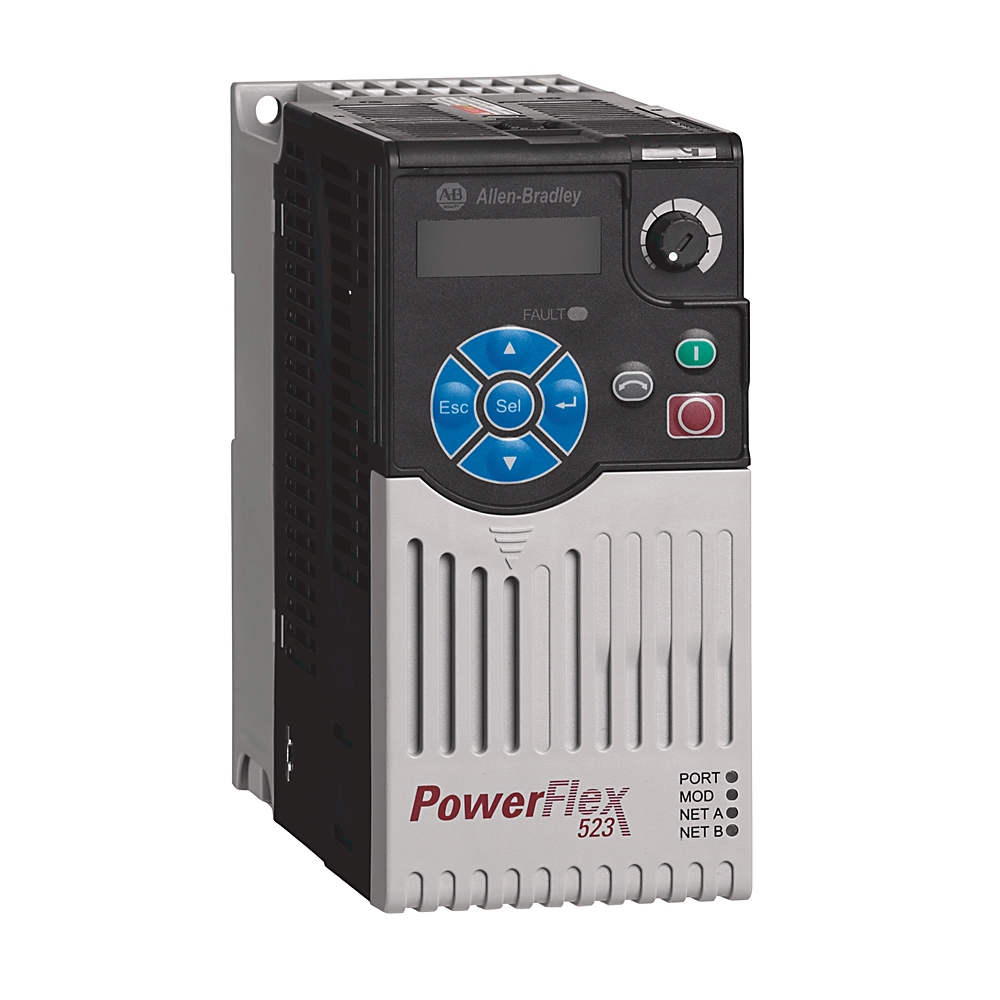
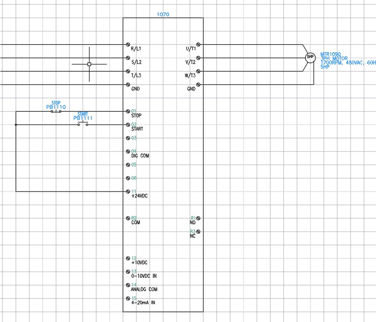
We will get into VFD’s later but typically the schematic symbol will show the terminal points and what is connected to them. Also what should be included for digital and analog signals is what their function is. The top four wires show the input power signals (R/L1, S/L2, T/L3, GND) and output power signals to the motor (U/T1, V/T2, W/T3, GND). Sometimes the power signals are separated from the I/O (Inputs and Outputs) of the drive. This is all dependent on the engineer or the company. There a parameters to VFD that need to be programmed to make it function the correct way. This will be discussed at a later point but for know you should know that basics.
TODAYS SYMBOLS
I am not including a symbol for VFD’s since these can vary for each drive. There are other symbols that also vary between the manufacturers, engineers, and companies.

Leave a comment